- Introduction
-
Low frequency noise generated by aircraft during pre-takeoff, takeoff, landing and post-landing operations equates to high levels of undesirable ground noise pollution. This phenomenon is gaining heightened popular interest among air transportation specialists and agencies as urban settlements and airports expand beyond post-war city limits to meet demands of the 21st Century. Several European airports including Paris, Frankfurt and Munich are seriously investigating these profound impacts on future airport activities and local environments.
Amsterdam Airport Schiphol’s (AAS) Polder Runway 18R-36L best exemplifies the disturbance caused by low frequency ground noise under specific atmospheric and topographical conditions.
Whispering Wind is an innovative passive and active architectural proposal combating and mitigating low and broadband (31.5Hz to +200Hz) frequencies generated by larger and / or older aircraft engines and cooling systems. The proposal prioritizes noise attenuation and deflection / scattering of undesired wavelengths to enhance the quality of life and lifestyles in the Hoofddorp settlements. It introduces the use of large Helmholtz resonators capable of creating a 12m virtual extension above and beyond the proposed landscape and large parabolic absorbers and sound catchers to increase surface absorption areas along the runway.
To meet the AAS’s targets on future expansion Whispering Wind adapts unique sustainable solutions towards ground noise mitigation, environmental and economic conservation and soil & water management by using tested and proven materials to form the main landscape and by introducing surge flood reservoir capable of accommodating plug-in floating barge developments. The vision capitalizes on negative connotations attributed to ground noise by transforming them into assets suggesting novel high-tech facilities while addressing new and future airport technologies.
The formal / functional design qualities of the Whispering Wind facility mould themselves to the polder landscape and airport by taking on aerodynamic shapes defined by stringent acoustic, environmental, programmatic, economic and legal requirements imposed on the site. The innovative use of landscaping, geometry, materials and alternative energies defines a new generation of air travel aesthetics and lifestyles transforming rumbling engines into whispering wind.
- Architectural precedence
-
In 1964 Bernard Rudofsky presented Architecture Without Architects at the MOMA in New York City. The exhibition and publication was greeted as a window onto non-pedigreed architecture and as a breath of fresh air by architectural academics. Rudofsky had no word to describe this newly rediscovered architecture.
Rudofsky suggests that architecture designed by trained architects is synonymous with the “Who’s Who of Architects” (Rudofsky 1964), formally rooted in history, functions mechanically and is detached from its environment. Non-pedigreed architecture is timeless, human and exquisitely adapted to its surroundings. Rudofsky’s message reveals these notions through architectural landscapes, building technologies, materials, lifestyles and cultures in which the house is redefined by “untutored builders in space and time” (Rudofsky 1964) – time being a space for creation, maturing, reflection, shifting and shaping the architectural patinas. For lack of a better term Rudofsky coined this Architecture Without Architects.
Wouldn’t it be beneficial to explore Architecture WITH Architects, by reaching beyond traditional architectural discourses and tools to address core issues such as population expansion, resource and waste management, alternative energies, material and construction efficiencies defined by their contexts. Might not such a discipline be referred to as the Digital Practice and the Sustainable Agenda?
- Plan of approach
-
Whispering Wind is a proposal developed by a Professional and Academic Alliance. The team is led by CDMB Architects and brings together leading researchers and professionals from the fields of Areoacoustics, CFD in Aerospace Technologies, International Business Economics, Structural Design, Digital Fabrication and CAD/BIM Design Coordination.
Our strategy takes apart the problem, analyses the components to recompose them in unexpected ways. Experience demonstrates that avant-garde and innovative solutions arise out of transforming deficiencies into assets. The design approach is based on a proof of concept structure.
The key question is: how can one create a sound barrier that must appear 32m high to sound for it to function while being 20m high to fit all air traffic safety and zoning requirements? This entails developing passive sustainable design solutions. Whispering Wind does develop new or untested systems; it adapts technologies i.e. Helmholtz resonators are based on proven acoustic principles found in ancient architecture and today’s most sophisticated aircraft engines. By employing the latest Aeroacoustic & CFD solvers we are capable of tweaking the design’s shapes and elements mitigating atmospheric propagation of ground noise.
The structural design approach aims at reducing construction costs, material waste and maintenance costs by adapting local Dutch construction methods & materials found in dykes and roadways. Further cost reduction is expected by implementing high standard parametric design and mass customization modes of fabrication.
One of our major concerns is air traffic safety. We are applying advanced CFD solvers to identify potential areas of air turbulence around the Polder runway resulting from the new structure. The design meets and exceeds the required air safety and local zoning authorities’ regulations. Our proposal does not require shutting down or diverting air traffic from the Polder runway during construction.
- Project Description
-
The main structure designed to mitigate low frequency ground noise propagated by specific atmospheric conditions is a wing-like shape serving the following functions:
- Attenuates low frequency ground noise emission power by 10dB.
- Embraces the future development and water management zone.
- Establishes a landmark while blending into the landscape.
- Provides R&D, educational & green recreational zones.
- Shapes airflows free of turbulence across the runway.
The wing shape literally fits within the legal envelop formed by the landing and takeoff requirements of the runway. Its highest point 20m is situated near the 36L runway position approx. 290m away from the runways centerline and gradually slopes down to ground level on either side. The proposed extensions beyond the proposed site boundaries anticipate possible future human settlements or expansions of Hoofddrop-Noord further into the Haarlemmermeer region. An acoustic masterplan indentifies acoustical and barrier zone limits in plan and section by applying a color coding systems. The masterplan is used to locate appropriate structure heights and noise levels. Consequently the proposed design moulds itself within these zones. The wing is a park like space covered by naturally groomed vegetation. The design creates its own micro climate which resembles in the vegetation.
- Noise Reduction
-
The CAA Analysis originates from a tightly knit collaboration between the architects, aeroacoustic, CFD and structural engineers exploring ancient technologies and state of the art jet propulsion mechanics. This leads to design specifications for large passive sound attenuators known as Helmholtz resonators that virtually extend the predefined site limits set by aviation safety regulations and the local authorities. The resonators further attenuate sound by creating a virtual vertical extension over the facility, a gain of 12m or more, effectively making the 20m structure appear like a 32m impediment to the sound energy by forcing it away from the ground.
- Sustainability
-
To successfully reduce noise levels with the use of passive acoustic sound attenuation devices we propose using local resources, materials and building techniques such as cut and fill and EPS blocks to arrive at low cost low maintenance sustainable construction solutions. Once again by tapping into the AAS brief and legal requirements set on future expansions at the airport we propose transforming the remaining area of the 60ha into a surge flood reservoir. This would immediately relieve the AAS from any further water management requirements permitting investments in more desirable areas of the ASS grounds without relinquishing valuable property to such water management. We propose developing a barge like plug-in development area similar to ideas currently explored in other Dutch regions including Hoofddrop. The reservoir is only filled during flooding seasons. By carefully planning the barge placements and functional aspects the area could benefit from new water storage, office, warehouse, parking and other facilities. These types of flexible spaces do not require major foundation work and will be required to explore and adapt possible sources of renewable energy. This sets up the possibility of developing a small scale self-sustained ecosystem typical of the polder regions that does not attract migratory birds.
- Innovation
-
The innovative aspects reflected throughout the project are synonymous with keywords like: passive systems, Helmholtz resonators, parabolic absorbers, sound catchers, low cost-low maintenance, surge flooding, reservoir, water management, plug-in facilities, flexibility, multipurpose spaces, EPS, renewable energies, green ground covers, biodiversity, digital tools, mass customization, R&D, education, and recreational activities to name a few. What makes them unique to this project is their ability to transform the complexities of the site and problem with ease into tangible and articulated solutions.
The use of digital tools in a BIM environment leads to streamlined communication between all parties involved while keeping the design requirements well under control. The implementation of such workflows is critical at the beginning of the research and design process. The most important tool remains the WorldWideWeb. It is often posited that what makes the human species different to all others is its ability to create tools and communicate via languages. The WWW is used to manage data via blogs and wikis to communicate all aspect of the project. It is a space for researching and disseminating information. The emerging opensource attitude over proprietary information may lead to “the true” digital revolution. All the tools developed for the Whispering Wind Fig.1 project are made available online free of charge.

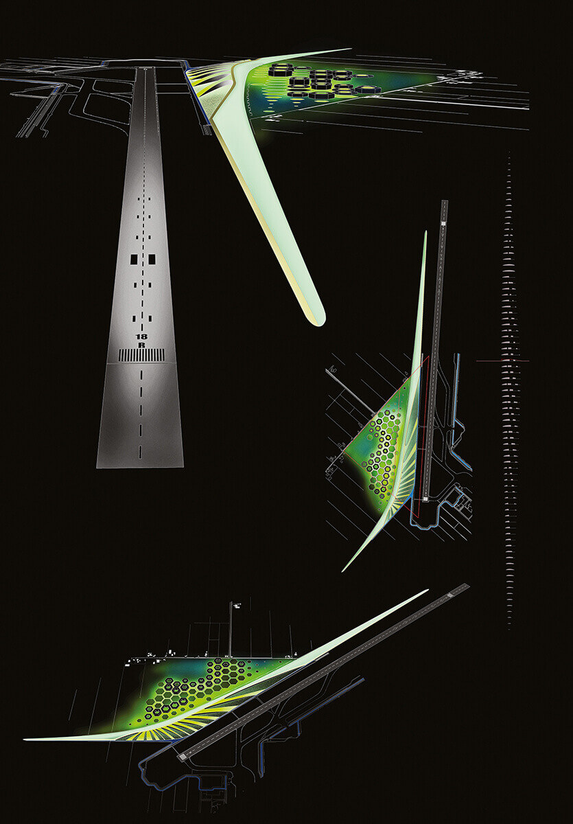
Figure 1: (Left to Right) Whispering Wind Site plan, Approach View & Axonometric.
- Icon
-
So-called iconic or landmark qualities can originate from bold formal concepts, emotional acts and / or purely rational principles; or they can result from adaptation to their environment. Whispering Wind sits quietly along the edge of the Polder Runway embracing the dynamic qualities of AAS and the Haarlemmermeer region while addressing 21st Century lifestyles.
- CAA analysis of the noise reduction facility including the insertion of large Helmholtz resonators
-
Introduction
Passive Acoustic treatments are a standard technique for internal surfaces of the aeroengine today. So why not use treatments to reduce aircraft ground noise? The low frequency noise addressed here requires different scales for the acoustic lining; the lining of ground surfaces and acoustic fences are not expected to be as efficient without lining the nacelle. The application of large resonators to improve the acoustics of a building goes back to the ancient Greek theatres using vases. The technique was rediscovered by the master-builders of the Middle Ages for their Cathedrals using large resonators fixed into the wall for the same purpose. The treatment of the top edge of acoustic screens was first proposed by Möser[2]. Though the treatment addresses higher frequencies, than intended here, the concept seems to be promising. The current concerns are the application of impedance on top of an acoustic fence in order to improve the absorption of sound directed towards the ground. The main source of sound is expected to be an aircraft at take off from the runway, exciting low frequency noise. The characteristic of this noise has been investigated systematically by Pollenske et al.[4] According to the results found herein, the major contribution to the noise is found in the low frequencies around 200 Hz. As the results are A-weighted, the real maximum may be at a lower frequency. The lower frequencies are more difficult to shield from the ground, as they are more diffracted than higher frequencies. Thus, only low frequencies are investigated and the measures are expected to shield high frequencies better than observed with the low frequencies. The digital CAA solver TUBA[1, 6] of TU Berlin is used, to compute the radiation including all flow effects and the acoustic treatment. The acoustic treatment is modelled by the EHR[7] model.
Results
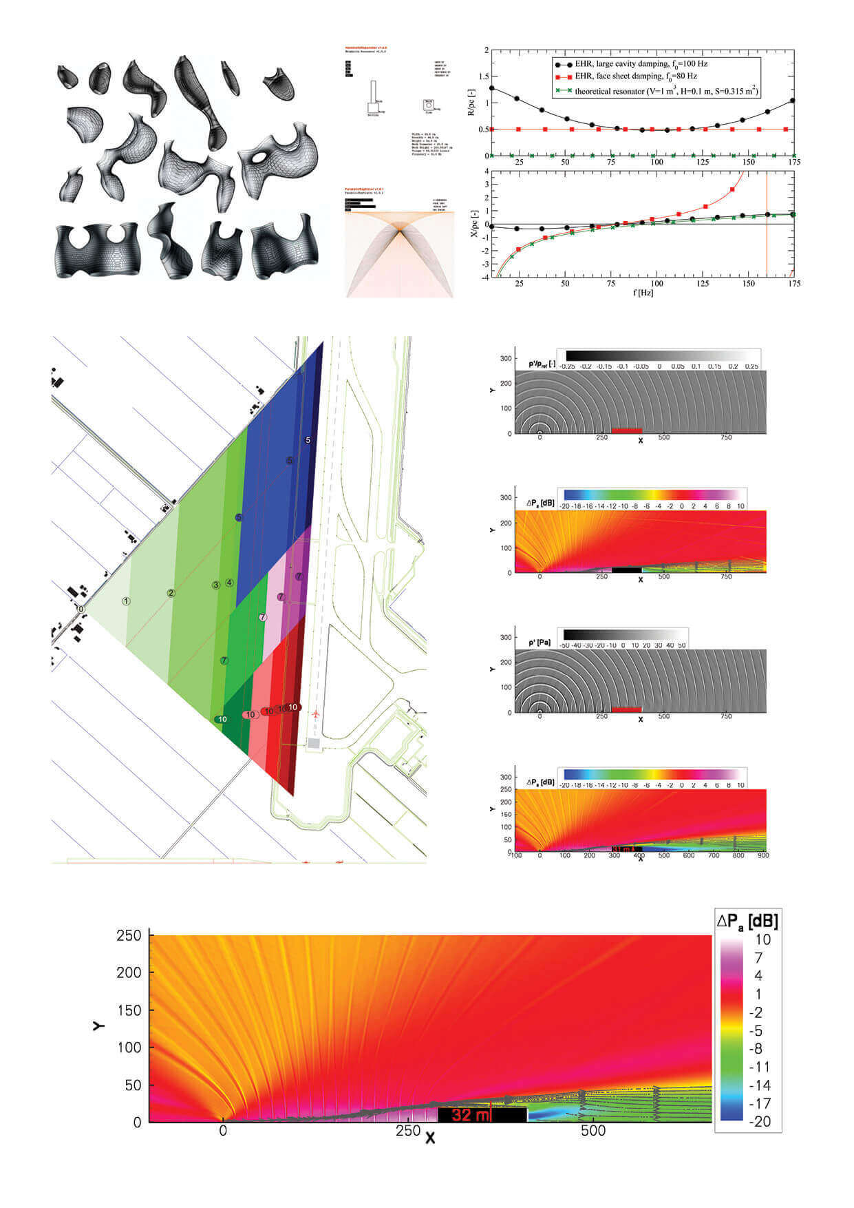
A simplified geometry is used to study the effect of the installation. A fence of 20 m height and width of 122 m is installed in a distance of 290 m from the runway. Different situations are considered. First the creation of a zone of silence behind the building is investigated without flow. Then the situation with wind is studied considering a typical wind speed of 20 km/h at 13 m, blowing off the runway towards the settled areas. This is considered as the critical situation, because the related atmospheric boundary layer leads to a refraction of the sound waves towards the ground. Herein u0~h1/7 is considered as template for the atmospheric boundary layer.
Due to the increased virtual height of the fence, the diffraction by the atmospheric boundary layer towards the ground is too weak to get the sound back to the ground again. Finally, due to the upper surface treatment a zone of silence is created behind the building, which produces < −10 dB attenuation at an observer position 1 km away from the runway for the low frequency range considered here. Higher frequencies are better shaded due to the reduced refraction. Due to the characteristics of the human ear, the low frequencies are depreciated further. This good result is transferable to observers further away from the runway, as the higher amplitude noise passes at a very high altitude and is not so strongly influenced by the atmospheric diffraction.
Conclusion
It is shown, that a non-treated 20 m high building or earthwork at 290 m distance from the runway is not able to produce the desired attenuation of low frequency noise reduction at a distance of 900 m from the runway. The same building with a passive acoustic treatment on its upper surface is able to produce an attenuation of 10 dB Fig.2. The treatment can be practically achieved for example by the application of large resonators or even decorative large vases.
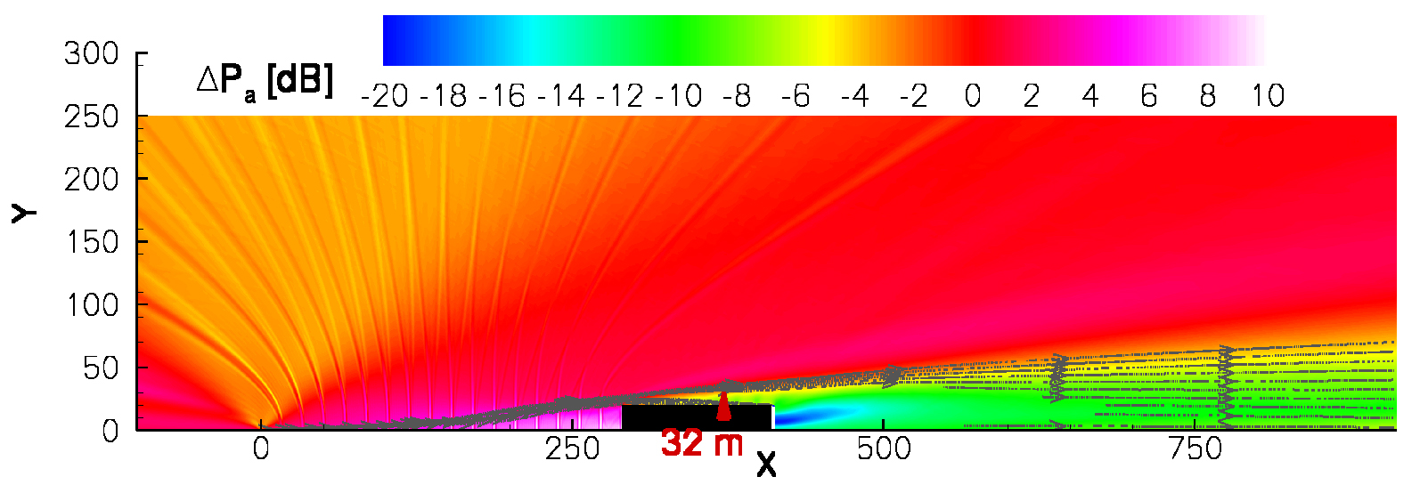
Figure 2: Average sound power attenuation with wind and with liner for f = 10, 20, . . . 90 Hz.
The pathway of the acoustic energy over the fence is visualized as gray traces.
- CFD Flow Field Analysis
-
Introduction
The reduction of aircraft ground noise during take-off and landing operations is of paramount importance. Acoustic fences near the runway can be used to reflect the noise from airplanes. They are very efficient if the height is designed properly, i.e., height greater than the wavelength of lowest frequencies and placed near the noise source (> 10 m for f = 34 Hz). On the other hand simple noise reduction fences near the runway negatively impact safe take-off and landing procedures of airplanes, due to the massive blocking of crosswinds compounded by strong shear flows above the fence. An improved design has to be used, meeting all requirements. The proposed Shiphol noise reduction facility (NRF) is placed approximately 300m from the runway with maximum height of 20m and a smooth shape to reduce the risk of flow separation and guide airflow down to the ground. The aerodynamic performances are investigated in this report.
Flow field simulation setup
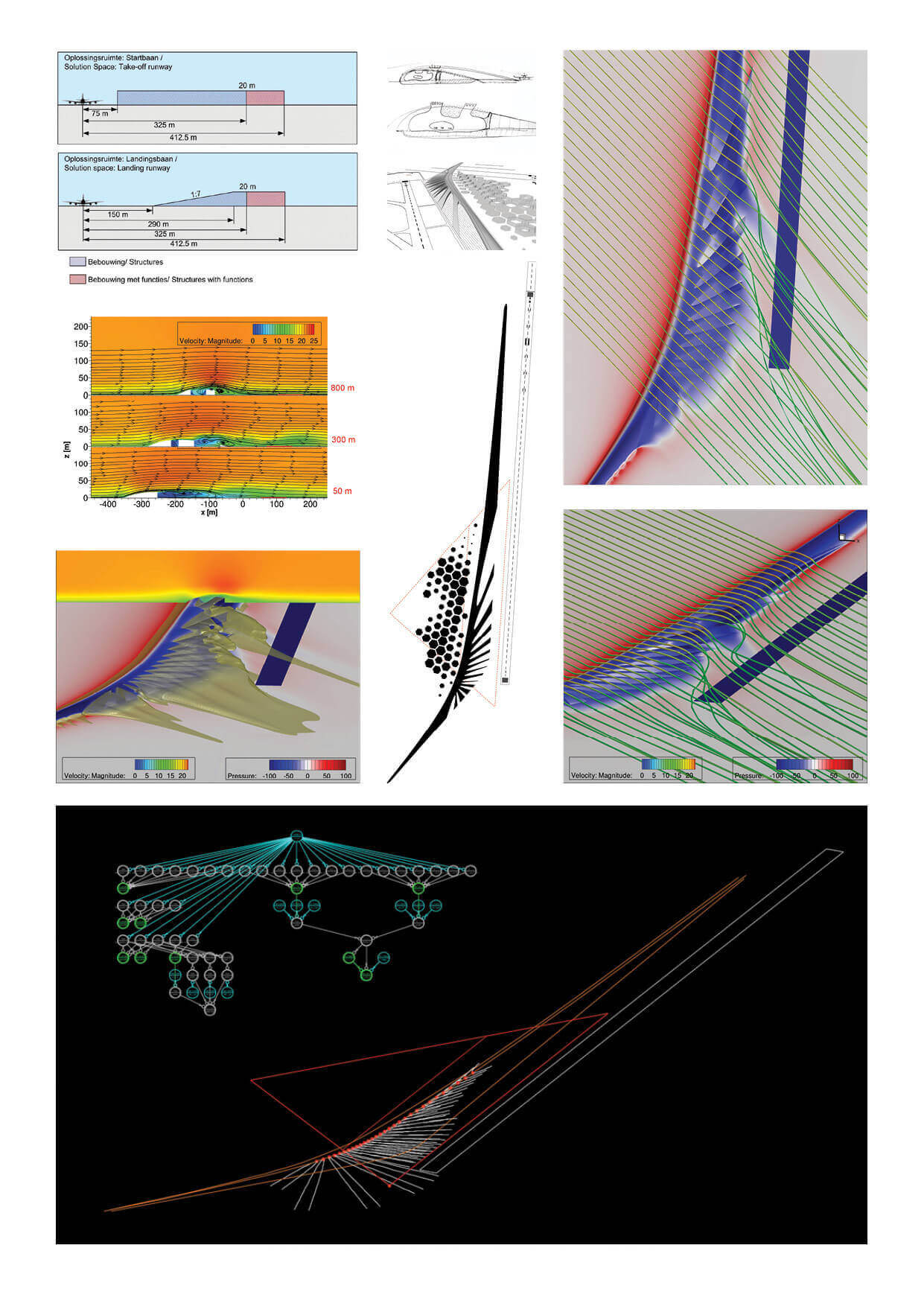
The setup includes a simplified three-dimensional model of the NRF based on geometries featured by Pottmann[3], including the parabolic acoustic cut-out sectors facing the runway. The total dimensions of the NRF are approximately 4300m from north to south (parallel to the runway) with a maximum width of 220 m. In Fig. 1 (left) the NRF is shown together with runway 18R (north) 36L (south) in orange. The computational simulation hull surrounding the model is 10,300 m x 7,100 m x 1,000 m large with an unstructured trimmed cell mesh of approximately 8.7 million cells. Near the NRF the volume mesh size is 1m with a prism layer of 1m height and 6 cells to properly resolve the boundary layer flow effects. We used a grid coarsening on the outer area. In the distance areas field the mesh is typical 50 m large with a prism layer height of 20 m.
The flow conditions mimic a simplified steady atmospheric boundary layer of approximately 40m in height with maximum velocity of 21.3 m/s from Northwest. The velocity at 13 m over ground is about 19 m/s. The incompressible flow field is calculated by solving the Reynolds-Averaged Navier-Stokes-equations (RANS) using the SST-k − w turbulence model calculated with Starccm+ from CD-adapco.
Results
Over the NRF the flow accelerates, and the wall pressure decreases (blue color). If the flow is completely attached over the entire building (= no separation of the flow) one can see a pressure rise directly after the building (red color) – this is clearly visible on the northern and south-western extensions. In these areas the NRF shows no dramatic impact on the overall flow field, the take-off and landing conditions will be affected to an irreducible minimum. At the mid-section of NRF (near southern end of runway 36L) the flow separates, the blue colored low pressure area smears out into the runway’s direction. In this area the streamlines are accelerated towards the south, this indicates vortex structures orientated in the flow directions. In Fig.3 (left) the swirled streamlines are clearly visible.

Figure 3: Wall pressure in blue-red gradient color scale.
Left: Detail view with colored velocity magnitude streamlines. Right: Iso-surface of velocity magnitude at a value of 10 m/s.
Conclusion
It can be stated that there is only an impact of the NRF on the flow near the southern part of the runway 36L (first 500 m) for the northwest flow case – the boundary layer shows an increased height. On the other hand the flow is attached in this area and the maximum velocity difference to the normal flow conditions is less than 10 m/s. The NRF is not critically affecting take-off or landing airplanes under these conditions. The major part (2800 m) of runway 18R and southwards is not affected by the NRF.
- Conclusions
-
The natures of problems are ever more complex as technologies and lifestyles evolve. 100 years ago there was no need for an airport let alone a noise reduction facility. These manmade problems consume vast quantities of manpower and energy when tackled with conventional design procedures. The digital medium enables us to share information instantly and across the team. This saves us time and money so we can focus on the critical questions at hand. We find ourselves spending more time thinking, discussing and framing possible questions & solutions. Relationship based modeling, scripting languages and simulation tools offer greater freedom in exploration and creation. This leads to meaningful performance driven architectures closely rooted to the original revelations made by Rudofsky[8].
BIM workflows coupled with ideas of mass customization and rapid prototyping may lead to more localized building solutions. We find ourselves at a point of redesign. Our economic and social models are no longer keeping pace with global changes. We are on the verge of defining a new chapter for the human species. The new design models and tools are opensource like Processing[5], shared between professionals, academic researchers, students and the layman. This may potentially lead to greater design innovation.
Whispering Wind’s goal is to attenuate noise of large aircraft and guarantee air traffic safety; more importantly Whispering Wind is an architectural prototype exploring closer integration of complex systems offering greater connections to nature and our environment.
- References
-
[1] Li, X.D. ; Schemel, C. ; Michel, U. ; Thiele, F.: Azimuthal Sound Mode Propagation in Axisymmetric Flow Ducts. In: AIAA Journal 42 (2004), October, Nr. 10, S. 2019–2027
[2] Möser, M.: Die Wirkung von zylindrischen Aufs¨atzen an Schallschirmen. In: Acta Acoustica united with Acoustica 81 (1995), S. 565–586
[3] Pottmann, H. ; Asperl, A. ; Hofer, M. ; and Kilian, A. ; (Ed.): 2007, Architectural Geometry, Bentley InstitutePress.
[4] Pott-Pollenske, M. ; Dobrzynski, W. ; Buchholz, H. ; Almoneit, D.: Characteristics of Noise from Aircraft Ground Operations. 2007. – AIAA 2007-3560
[5] Reas, C. and Fry, B. (Ed.): 2007, Processing, A Programming Handbook for Visual Designers & Artists, MIT Press, Boston.
[6] Richter, C. ; Thiele, F. ; Li, X. D. ; Zhuang, M.: Comparison of Time-Domain Impedance Boundary Conditions for Lined Duct Flows. In: AIAA Journal 45 (2007), Juni, Nr. 6, S. 1333–1345
[7] Rienstra, S.W.: Impedance Models in Time Domain, Including the Extended Helmholtz Resonator Model. Mai 2006. – AIAA Paper 2006–2686
[8] Rudofsky, B. (Ed.): 1964, Architecture Without Architects, Museum of Modern Art, New York.